(Updated March 17th 2002)
This project was born when, following the death of Dennis, G4OO in 2000, it was suggested that some of his gear should remain in use in the Spalding and District Amateur Radio Society clubroom, as a memorial to Dennis, who was one of the founders of the Society.
Also, the Society members hold a Sunday morning topband AM net, as no AM facility is available at the clubroom, and also as Dennis was a regular on the net, we thought that something to use on this mode would be appropriate.
Amongst Dennis' gear was this receiver and transmitter.
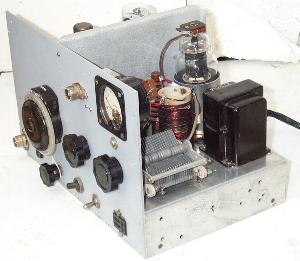
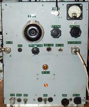
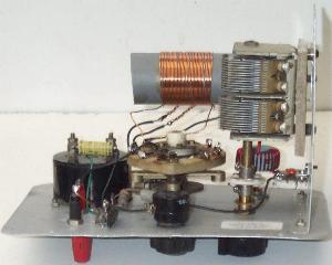
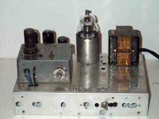
The receiver was a strange beast indeed, built on what appears to be a commercially manufactured chassis, it uses Command receiver components, including the tuning dial and gang, front end coils and IF transformers. However, it uses miniature valves of the 6BA6, 6AM6 etc. variety, with an ECH81 mixer and an ECL80 audio valve. It had been much modified over the years, but what remains of the original wiring is very neat indeed, I think that it was either commercially made, or a very well assembled kit, but for what purpose? It tunes 3 - 6 Mc/s, as on the original command receiver. The clue was that, on the right hand side there is an empty space, with two holes in the front panel to take Belling sockets, this suggests that converters were fitted, maybe for two and four metres, so it was designed as a tuneable IF unit.
| Following appeals
for information on the receiver, Robin Holderness G3XDA
wrote:
I recognise that rx as one which
came from the late Brian Loveday, Weldon (near) Corby. He
died approx 3 or 4 years ago and I helped dispose of
most of his vast collection of bits & pieces. He
thoroughly enjoyed
experimenting/modifying/constructing, with interests from vlf up
to microwaves, and was a quiet but friendly person who
having retired spent a lot of time enjoying his
hobby. It is quite likely that with his vhf/uhf interests that it was a tunable IF. It has subsequently transpired that
the receiver was in fact built by Doug Hill
G8BEH. |
The transmitter consists of two chassis, a power supply and the TX unit itself, very obviously homebrew.
 Underside view of the PSU, as found. |
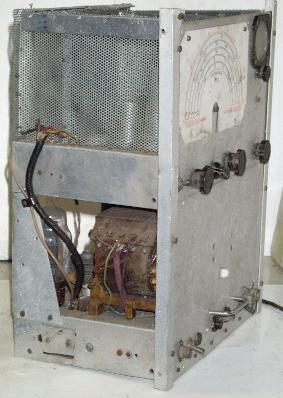
The TX had a crude screening cage made from the perforated zinc that was once used for "meat safes". It had been stored in a damp place for many years and was in a very sorry state indeed.
Restoration.
Where to start? Well, the theory "if you can't hear 'em, you can't work 'em" is a good one, so I started with the receiver. There was a great big space which had obviously once been occupied by a mains transformer, so I had a hunt round and found a Parmeko transformer with 250 - 0 - 250 and several 6.3 volt windings that would fit in the space, and, as there was a B7G size hole nearby, with a 6X4 rectifier a simple PSU was connected up. Soon, the heaters were all glowing nicely, and as the HT rose, noises, horrible noises, emerged from the on - board speaker. Not for long though, a bang, a lot of smoke, and an obnoxious smell filled the shack. Why didn't I reform the electrolytics? Well, I did actually, the problem was that the RX contained an inordinate number of 0.01µF red "eurocapacitors". Needless to say these were almost without exception leaky, and one of these was the source of the explosion. Most had to be replaced, and with this done, more promising noises emerged. In fact, tuning to 80 metres showed that the receiver was quite lively.
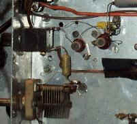
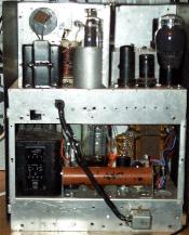
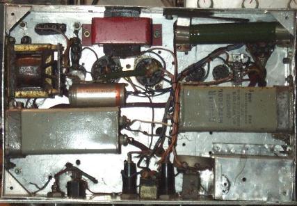
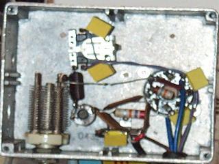
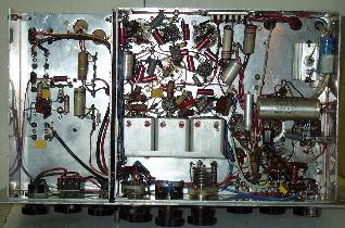 Underside of the Rx chassis, after some restoration. The topband converter and muting relay are on the left hand chassis. |
The receiver includes a product detector using an ECC81 (12AT7) and a separate BFO, and also a separate AVC amplifier, with two 0A81 type germanium diodes for AM and AVC detection. the latter has a switchable time constant, this combination provides absolutely superb SSB reception. A Q - Multiplier provides variable selectivity in the IF, which incidentally is the standard Command 1,415 kc/s, and with careful adjustment can provide selectivity as good as modern day transceivers. A few more mods and tweaks were required, these produced a very creditable receiver, with very little drift and very pleasant audio quality and which is very nice to use on the 80m band.
Topband.
The primary purpose of this project is to
provide a 160m station; as found this Rx covers 3 - 6Mc/s, so what
would be the best way around this? I decided against modifying
the front end coils as they were so nicely made it seemed a shame to
butcher them, also 80m coverage was already there and would be a
bonus.
The simplest way would be to convert topband signals to a
frequency already covered by the receiver, and as it had originally
been designed as a tuneable IF unit this seemed the best way
forward. A quick root through my stock of crystals produced one on
6,800kc/s, some simple maths revealed that using this, 1.8 - 2 Mc/s would
appear at 5 - 4.8 Mc/s (reversed tuning), and as this area is free of
broadcast stations, and is relatively quiet, this was the way
forward. 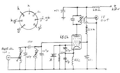
A simple converter using a 6BE6 (EK90) and the 6,800 kc/s crystal was built up on the blank chassis, using the circuit shown here. The bandpass input circuit was found necessary to prevent breakthrough of broadcast stations from the 25m broadcast band (6,800 + 4,800 = 11,600). This simple circuit is not excessively noisy, and provides enough sensitivity without an RF stage. A simple switching arrangement was added to allow the converter to be switched in or out as needed. An added bonus is that the local MW broadcast stations can be tuned in as well, by tuning further up the IF band.
Addition of a muting relay, and a few other minor mods were completed by Christmas 2000 and the receiver was used as the main shack receiver for topband and 80 for several months for testing. One further fault developed, AM reception became distorted on strong signals, this was traced to an open circuit 0A81 diode, the AVC detector.
The Transmitter.
Turning back to the transmitter, closer examination showed that a 'restoration' would not be feasible for several reasons, so I began to think along the lines of a 'rebuild'.
As mentioned above, the transmitter had been stored in a damp environment for some time, the zinc screening and aluminium chassis were both very corroded, as was the tuning gang of the Geloso unit. The dial cover and pointer for this were missing as well. The electrolytic capacitors were of course beyond redemption, and much of the wiring was in screened rubber insulated cable, the insulation crumbled away when touched. Also as it was the unit didn't cover topband!
So the decision was made to strip the unit completely and rebuild it as a topband transmitter using as many of the original components as possible, together with some others from Dennis' collection.
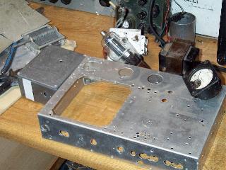 |
| The transmitter chassis, stripped of all components and cleaned ready for reassembly. Also visible are the diecast box for the rebuilt VFO, the meter, mod transformer and PA tuning capacitor. |
The TX and PSU chassis were stripped of all components and cleaned. The zinc screening was too brittle to reuse and was discarded, but most other components (except the electrolytic capacitors) were cleaned and tested, and found to be serviceable.
Now, Dennis by his own admission was not a craftsman in the art of either metalwork or soldering, as long as it worked well it was OK. Also, he was never satisfied with a project, always modifying, improving or pulling down and starting again, and, judging by the number of holes in the chassis, this rig had been no exception. So I saw no reason why I shouldn't carry on the tradition!
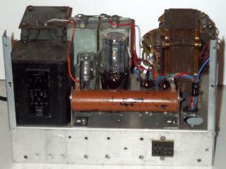
Beginning with the power supply, the transformers both tested OK, so I refitted them, together with the large choke and the two paper 8µF 1000 volt capacitors. This was all rewired, together with a 10Kohm dropper and a 0A2 for the 150 volt VFO supply, and a simple 12 volt supply for the relays. All outputs were made available at a 12 way Jones socket on the rear panel.
The microphone amplifier was also rewired, using new components, its output was also routed via the Jones socket.
 |
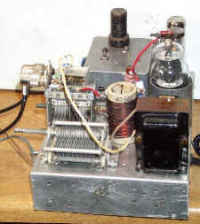
Transmitter chassis I had decided not to use the Geloso unit, both because of its condition, and because as it is it doesn't cover topband, so instead I built up a VFO unit into a diecast box that was amongst Dennis' components. It too had been used for several previous projects! I used a 6J5 triode in a standard Vackar circuit, supplied from the 150 volt stabilised supply and tuned with a 65pF Jackson variable capacitor from the same source. It tunes 1.75 - 2.0 Mc/s, with a view to using it on Topband and 80m (by doubling). An aluminium plate was fixed over the large hole in the TX chassis where the Geloso unit had been fitted, and the diecast box fitted on top of this. |
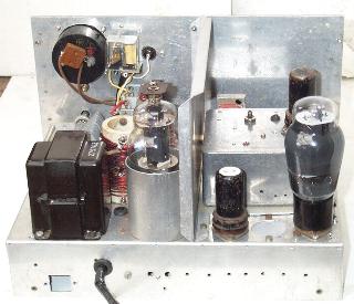
| The rebuilt power supply. The orange object is a 10Kohm resistor of some colossal wattage. |
At an early stage I had decided to retain the CW facilities, but as the intended use will mainly be AM, I planned to include a proper anode and screen modulation system. There were the remains of part of a Pye F27 base station amongst the junk, this provided a nice compact 25 watt modulation transformer and the 6V6 valves to drive it. These components were fitted to the TX chassis, the mic amp on the PSU was modified to provide a push pull output to drive them. This tested OK into an audio dummy load, so on now to the RF section.
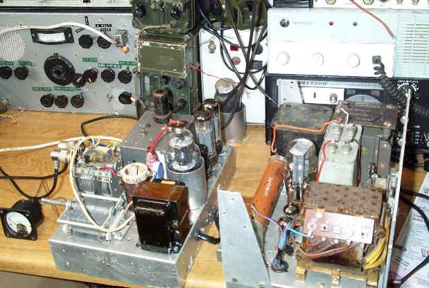
Transmitter chassis partly rebuilt, visible are the new VFO unit, modulation transformer and 807 PA valve in its screened holder. The 6V6 modulator valves are on the rear left of the chassis. |
Inside the VFO unit. The relay is to
control the standby/
netting facility.